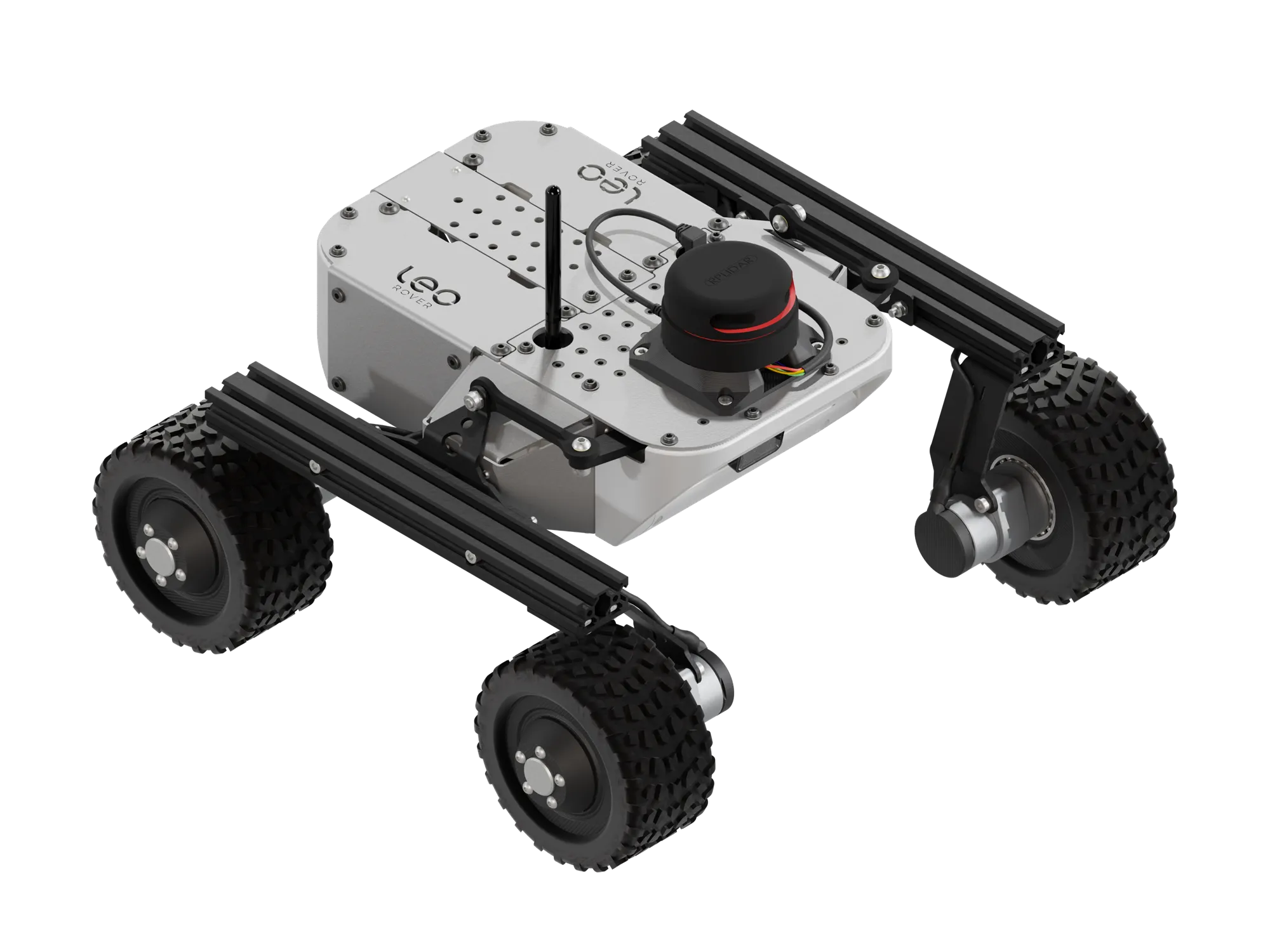
SLAMTEC RPLIDAR A2 Integration
This tutorial will guide you through the process of connecting a LiDAR sensor to your Leo Rover.
Light Detection and Ranging devices, or lidars for short, are mechanisms used for mapping the environment, object detection, tracking the speed of vehicles and in a wide range of other applications. In robotics 2D lidars, like A2M8 / A2M12, are used for things such as indoor SLAM (Simultaneous localization and mapping) or safety systems.
What to expect?
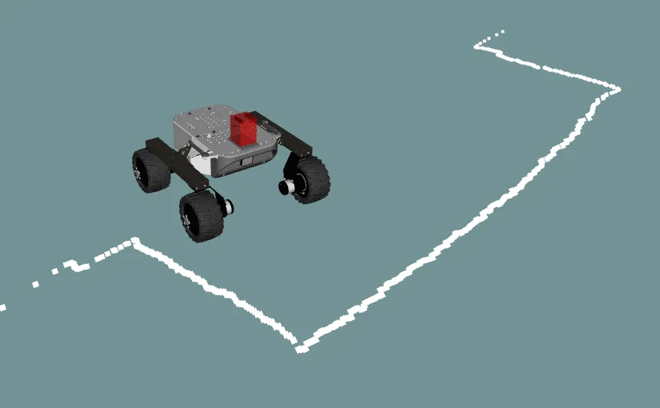
After finishing the tutorial you should be able to gather the lidar data from
the /scan topic and visualize it using RViz. Just like in the image below:
Prerequisites
Referenced products
Hardware integration
Mounting
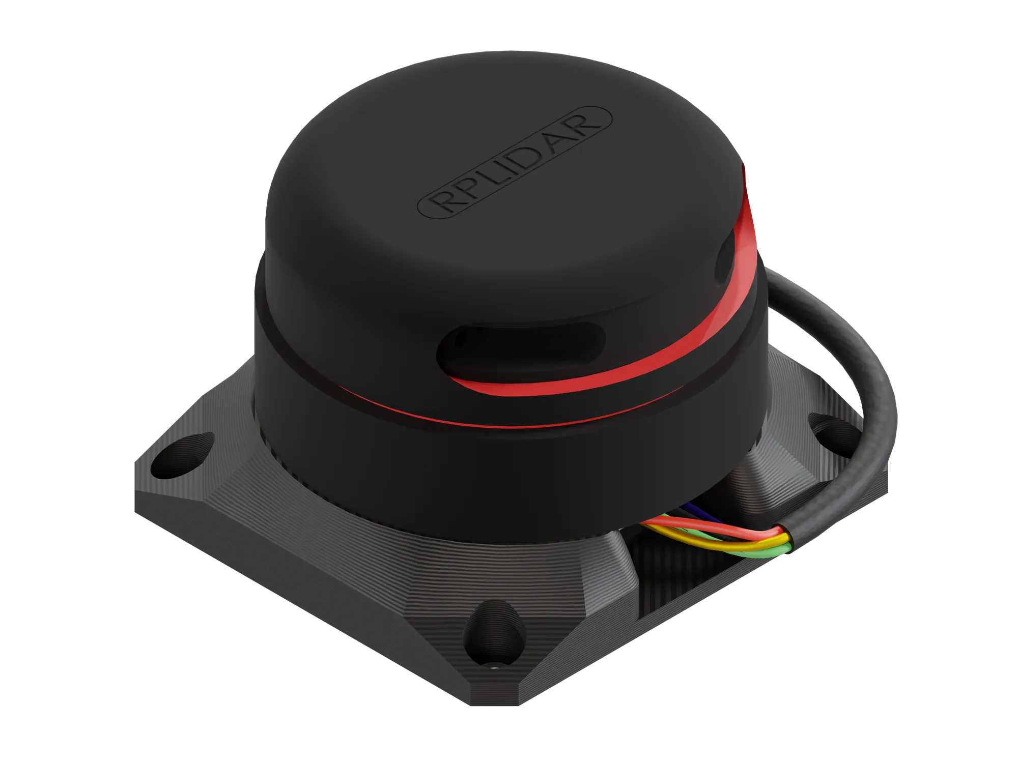
If you bought the integration from us, you can use the mounting adapter included in the package. It is designed to mount the RPLidar A2 on top of the rover.
Required components:
- RPLidar A2
- RPLidar USB-UART adapter
- RPLidar A2 adapter plate (can be found here: Addon adapters)
- USB micro - USB C cable
- M5 x 10 Allen head screw x4
- M3 x 6 Allen head screw x4
To mount the sensor:
- Insert the USB-UART adapter into the dedicated place in the printed mount.
Some USB-UART adapters allow you to choose the baud rate with a physical switch. If your adapter has such a switch, make sure to put it in the correct position for your RPLidar:
- For RPLidar A2 M12, set the baud rate to 256000 bps.
- For RPLidar A2 M8, set the baud rate to 115200 bps.
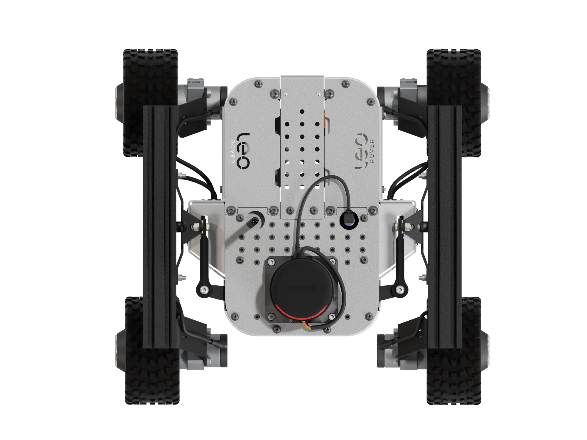
- Secure the RPLidar A2 to the 3D-printed mount using M3x6 Allen head screws. Make sure that the sensor is rotated correctly - the lidar cable should point towards the back of the rover. Image of correct mounting is presented in wiring section.
- Secure the subassembly to the Leo Rover using M5x10 Allen head screws.
If you don't have the integration kit, you can also 3D print the adapter plate yourself. Get the files from the Addon Adapters page.
The URDF model provided in this guide assumes the sensor is mounted using our adapter plate in the default position. If you mount the sensor in a different position, you will need to adjust the origin values in the URDF file accordingly so that the sensor is correctly positioned in the robot model.
Wiring
- Connect RPLiDAR A2 to USB-UART converter.
Make sure that excess cable is wrapped around the sensor so it does not obstruct LiDARs field of view.
- Connect USB-UART converter to Leo Rover via USB micro - USB C cable.
Correct assembly is presented in the image below.
USB connection provides power to the sensor and allows the data transfer. This means that no external power sources are necessary. With everything connected, you are ready to try out your new sensor.
Software integration
The first thing you can do is to make sure your device has the correct permissions and is available at the fixed path on your system. To do this, you can add the following rule to the udev service:
KERNEL=="ttyUSB*", ATTRS{idVendor}=="10c4", ATTRS{idProduct}=="ea60", MODE="0666", GROUP="dialout", SYMLINK+="lidar"
Paste these lines to /etc/udev/rules.d/lidar.rules file and reload udev rules
by typing:
sudo udevadm control --reload-rules && sudo udevadm trigger
Your device should now be available at the /dev/lidar path.
We want the sensor functionality to be available in the ROS ecosystem, so you should install a ROS package that provides a node for the sensor you are trying to integrate.
sudo apt install ros-${ROS_DISTRO}-rplidar-ros
Now, create a launch file that would start the node with a fitting configuration. Configuration varies depending on the RPLidar version.
- RPLidar A2 M8
- RPLidar A2 M12
<launch>
  <node pkg="rplidar_ros" exec="rplidar_node">
    <param name="serial_port" value="/dev/lidar"/>
    <param name="serial_baudrate" value="115200"/>
    <param name="frame_id" value="laser_frame"/>
  </node>
</launch>
<launch>
  <node pkg="rplidar_ros" exec="rplidar_node">
    <param name="serial_port" value="/dev/lidar"/>
    <param name="serial_baudrate" value="256000"/>
    <param name="frame_id" value="laser_frame"/>
  </node>
</launch>
Include your launch file in the robot.launch.xml file, so that your node will
start at boot.
In /etc/ros/robot.launch.xml:
<include file="/etc/ros/laser.launch.xml" />
Modifying the URDF model
Your robot should be aware of where the sensor is located and what space it occupies. You can ensure it does that by creating an URDF model of the sensor.
<?xml version="1.0"?>
<robot>

  <link name="rplidar_link">
    <visual>
      <origin xyz="0 0 0.0085"/>
      <geometry>
        <box size="0.080 0.087 0.017"/>
      </geometry>
      <material name="support">
        <color rgba="0.5 0.5 0.5 1.0"/>
      </material>
    </visual>
    <visual>
      <origin xyz="0 0 0.034"/>
      <geometry>
        <cylinder radius="0.038" length="0.041"/>
      </geometry>
      <material name="lidar">
        <color rgba="1.0 0.0 0.0 0.7"/>
      </material>
    </visual>
    <collision>
      <origin xyz="0 0 0.0085"/>
      <geometry>
        <box size="0.080 0.087 0.017"/>
      </geometry>
    </collision>
    <collision>
      <origin xyz="0 0 0.034"/>
      <geometry>
        <cylinder radius="0.038" length="0.041"/>
      </geometry>
    </collision>
  </link>

  <joint name="rplidar_joint" type="fixed">
    <origin xyz="0.0775 0 0"/>
    <parent link="base_link"/>
    <child link="rplidar_link"/>
  </joint>

  <link name="laser_frame"/>

  <joint name="laser_joint" type="fixed">
    <origin xyz="0 0 0.483" rpy="0 0 ${-pi/2}"/>
    <parent link="rplidar_link"/>
    <child link="laser_frame"/>
  </joint>

</robot>
And including it in the description that is uploaded at boot.
<xacro:include filename="/etc/ros/urdf/laser.urdf"/>
You can experiment with the URDF file and create a more representative model of the sensor by adding more visual and collision tags or by including meshes in STL or COLLADA format.
The last step is to either reboot the robot or restart the nodes.
ros-nodes-restart
Example usage
Reading and visualizing the data
The robot should now publish the
LaserScan messages
on the /scan topic. You can check the raw data that it sends by typing:
ros2 topic echo /scan
If you have ROS installed on your computer, you can get a more graphical representation of the data with RViz. If you don't have ROS, you can follow this guide:
Now, open RViz by typing rviz2 in the terminal, or, if you have the leo_viz
package installed, type:
ros2 launch leo_viz rviz.launch.xml
This will start RViz with visualization of the current robot model.
You can easily install the leo_viz package with this command
sudo apt install ros-${ROS_DISTRO}-leo-desktop
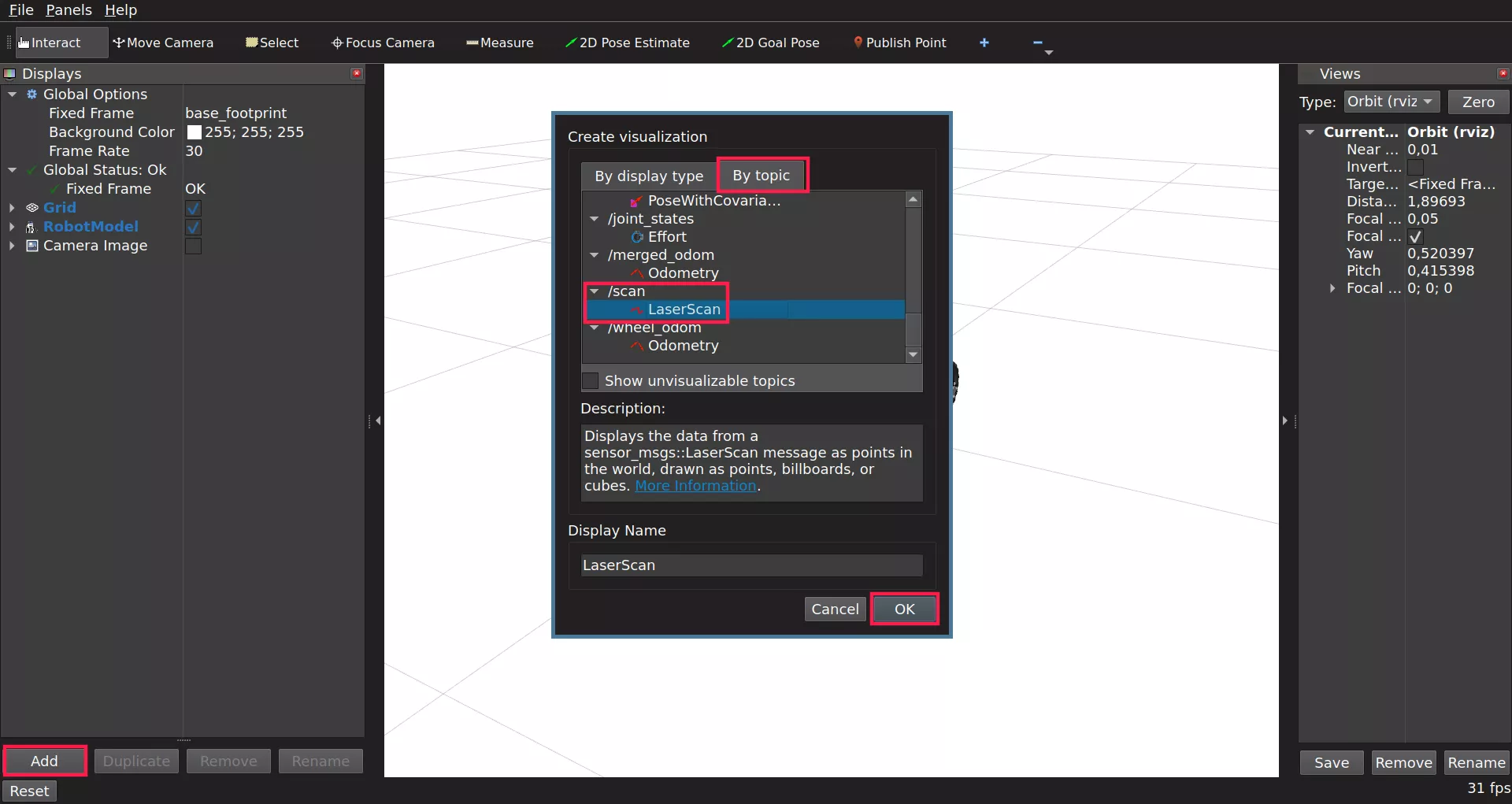
On the Displays panel click Add -> By topic and search for the /scan
topic. Choose the LaserScan display and click Ok.
Sometimes the scan data might not be visible as it will melt with the background. To fix this you need to change the color of the displayed laser. To do so, use the drop down arrow option from added LaserScan and set Color Transformer to FlatColor. As you do so, there will appear Color option which you can use to change the displayed laser.
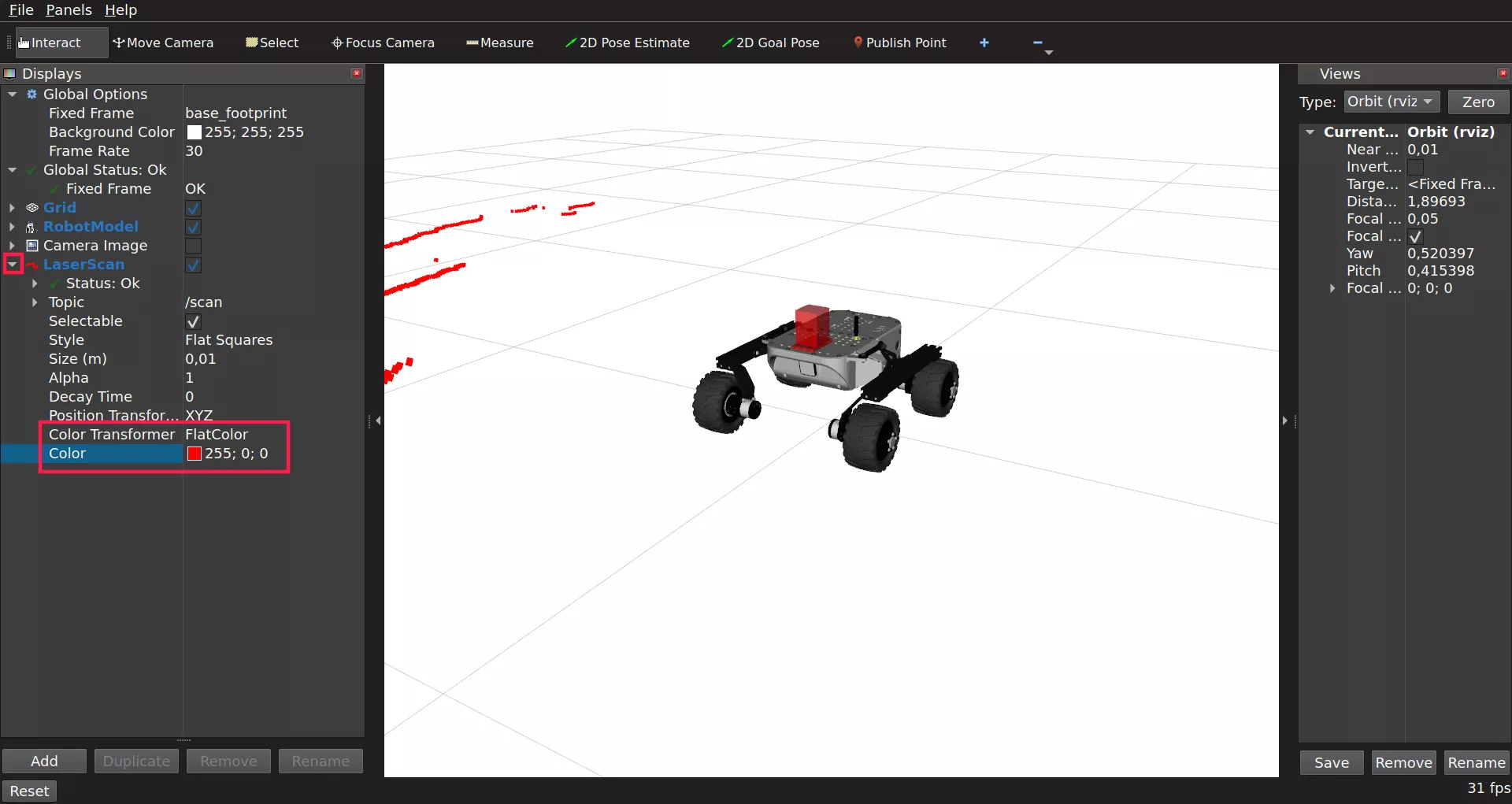
You should now be able to see the data from the sensor visualized as points in 3D space.
To put the points into the camera image, you can also add the Camera display.
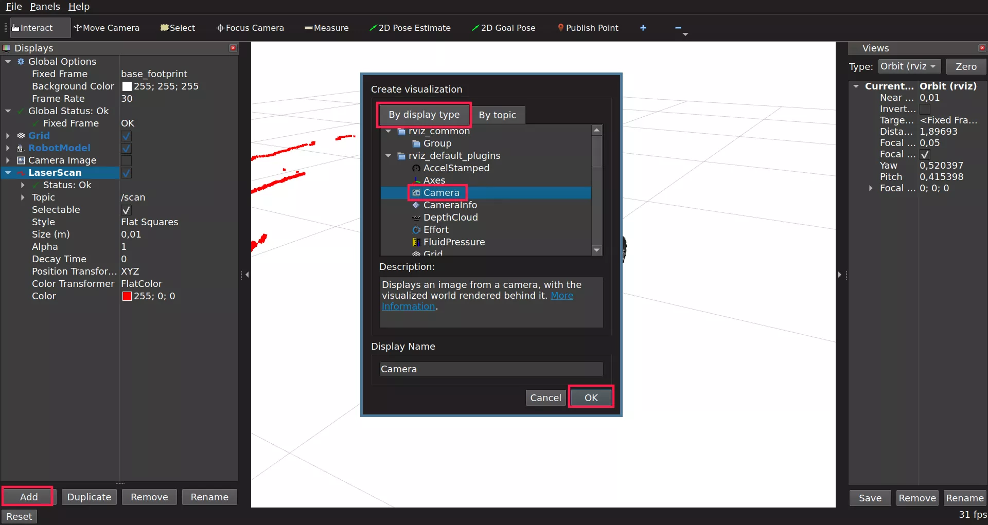
Be sure to select /camera/image_color as the Image Topic.
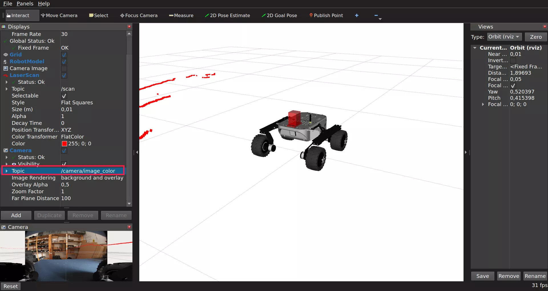
Here's an example end result:
What's next?
Lidars are commonly used in projects involving autonomous navigation, you might be interested in a tutorial about it.
They are however, not the only way of teaching a Leo Rover how to move on it's own. Check out our line follower tutorial if you want to learn more. You can also check our Integrations page for more instructions.